
8x8x8 LED Cube

Overview
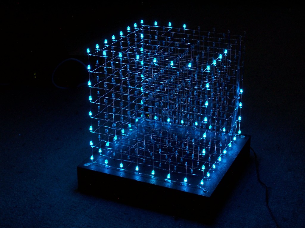
Another LED cube project, based on an ATMega32 controlling 512 blue 3mm LEDs
I've put a lot of time and work in the animations, but I think it was worth it.
Deutsche Projektbeschreibung auf mikrocontroller.net
Animations/Effects
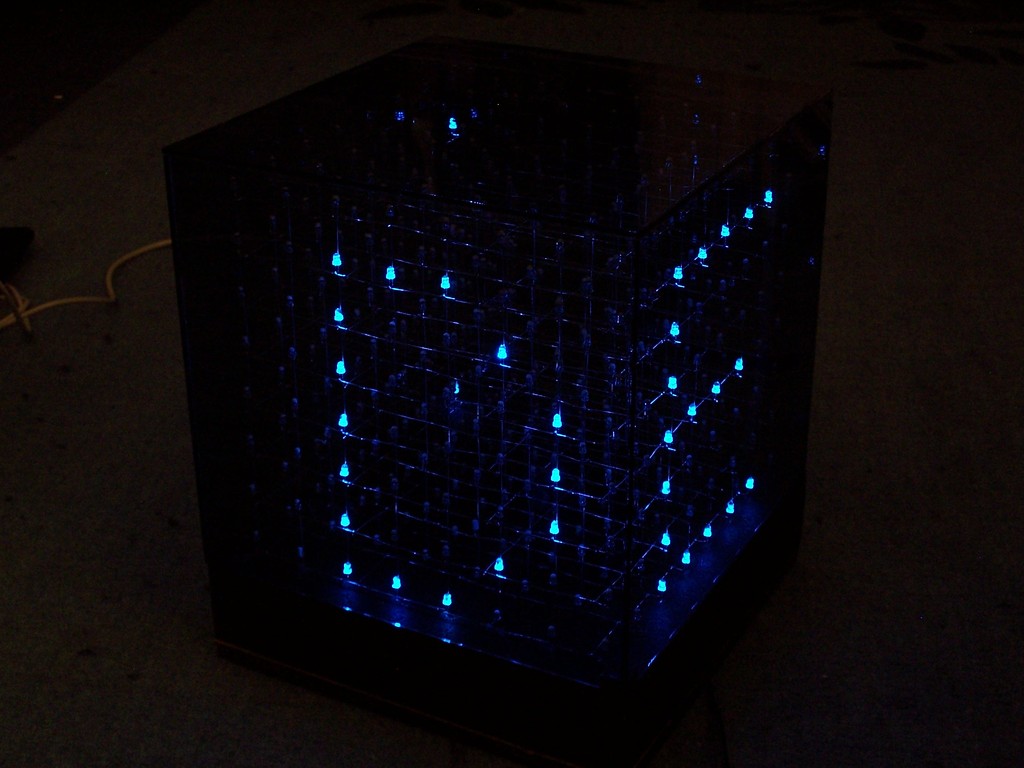
The software supports a large set of different animations, here are some of them.
Better watch the video...
- animated text:
All text functions support [A-Z][0-9][?.:!]
In this case each char comes in from the left side, rotates by 90 deg and is then moved to the front with some flash effects.
- text back to front:
Each char starts at the backside and moves quickly to the front.
- text belt:
Actually this is a 25x8 pixel layer which is mapped around the left/front/right of the cube. The string moves from the right to the left.
- 2 chars rotating:
2 fixed chars rotate around the center.

- walking man:
This is a really cool animation. At first, a door opens and a guy walks in. When he reaches the center, the environment starts moving while he walks, after some time it stops and the guy walks out of the cube.
- 2x2x2 cubes:
24 2^3 cubes moving around, fully automatic. For this effect an extra cube of [4][4] is created where the elements represent 2^3 cubes. This is later mapped to the large cube. Now one element and a direction is chosen by rand(). The cubes are moved until they hit the "wall" or another cube.
Watch the video on youtube
Construction

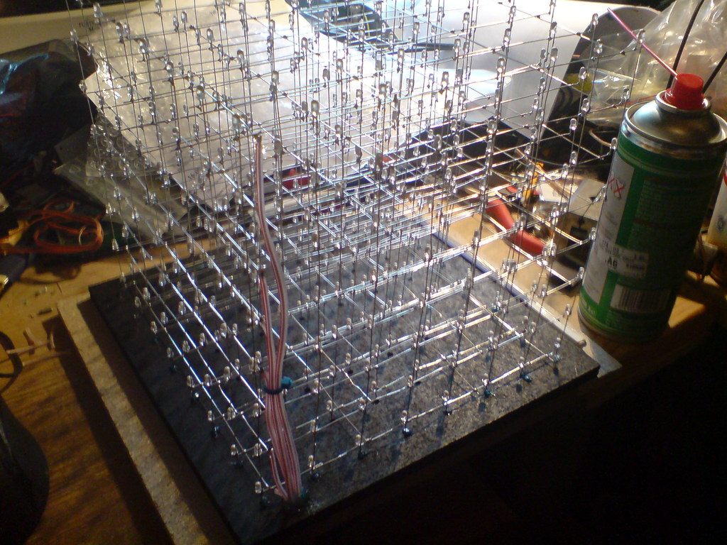
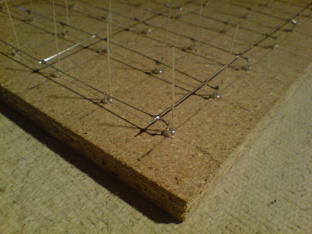
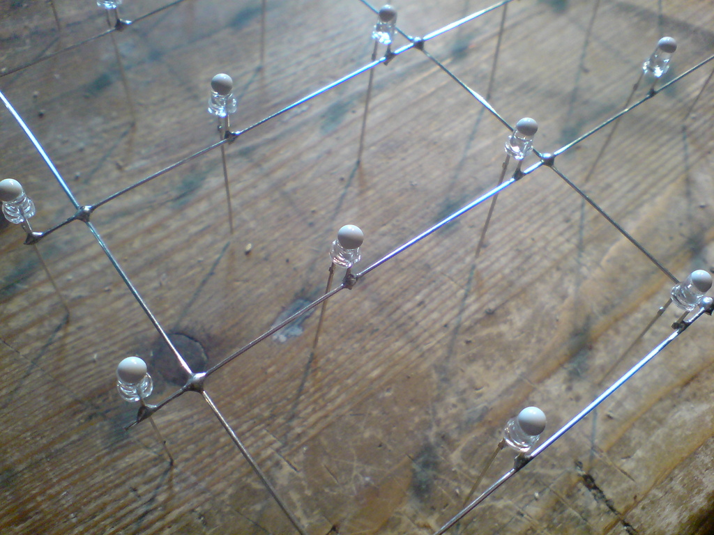
I started with drilling 64 3mm holes (distance between the holes is 30mm) in the ground plane, which is very helpfull for soldering the layers.
The cathode pins were cut and soldered together with 0,6mm silver wire.
I ordered 600 LEDs, that came in handy since some LEDs were broken and some were killed with the soldering iron (I soldered very close to the housing). This way I got exactly the same wavelength and brightness for those LEDs. And by the way, replacing a LED inside the cube is no fun, although its possible with a steady hand, a long soldering iron and tweezerz :)
Each layer was tested and finaly all layers soldered together.
I painted the ground plane black and glued the cube in it. Grey tinted glass is used for the cover.
Control Unit
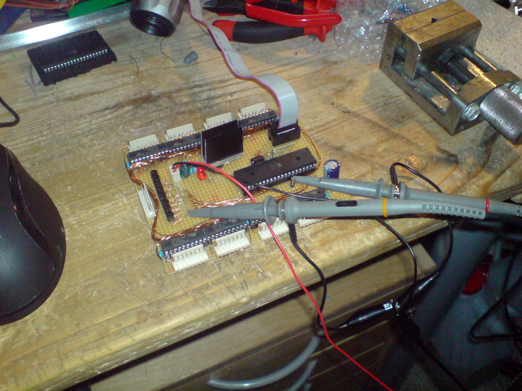
The control unit is quite simple, 3 ports of the Mega32 were used:
- one port controls 8 FETs for sinking the 8 ground layers
- one port is wired to all 8 8bit d-latch inputs
- the last port is used to enable the d-latch inputs
Since the d-latches are only able to sink or source 70mA on all 8 latches, I had to limit the diode current to ~9mA, which is fairly enough for this type of LED.
Here is the schematic for the controller board: scheme.
For my source code, the wiring should be like this: PC0 is the bottom layer, PC7 the top layer.
PD0 (Q0) sets the front bits, PD7 (Q7) the rear side. PA0 (U9) is the left side, PA7 the right side.
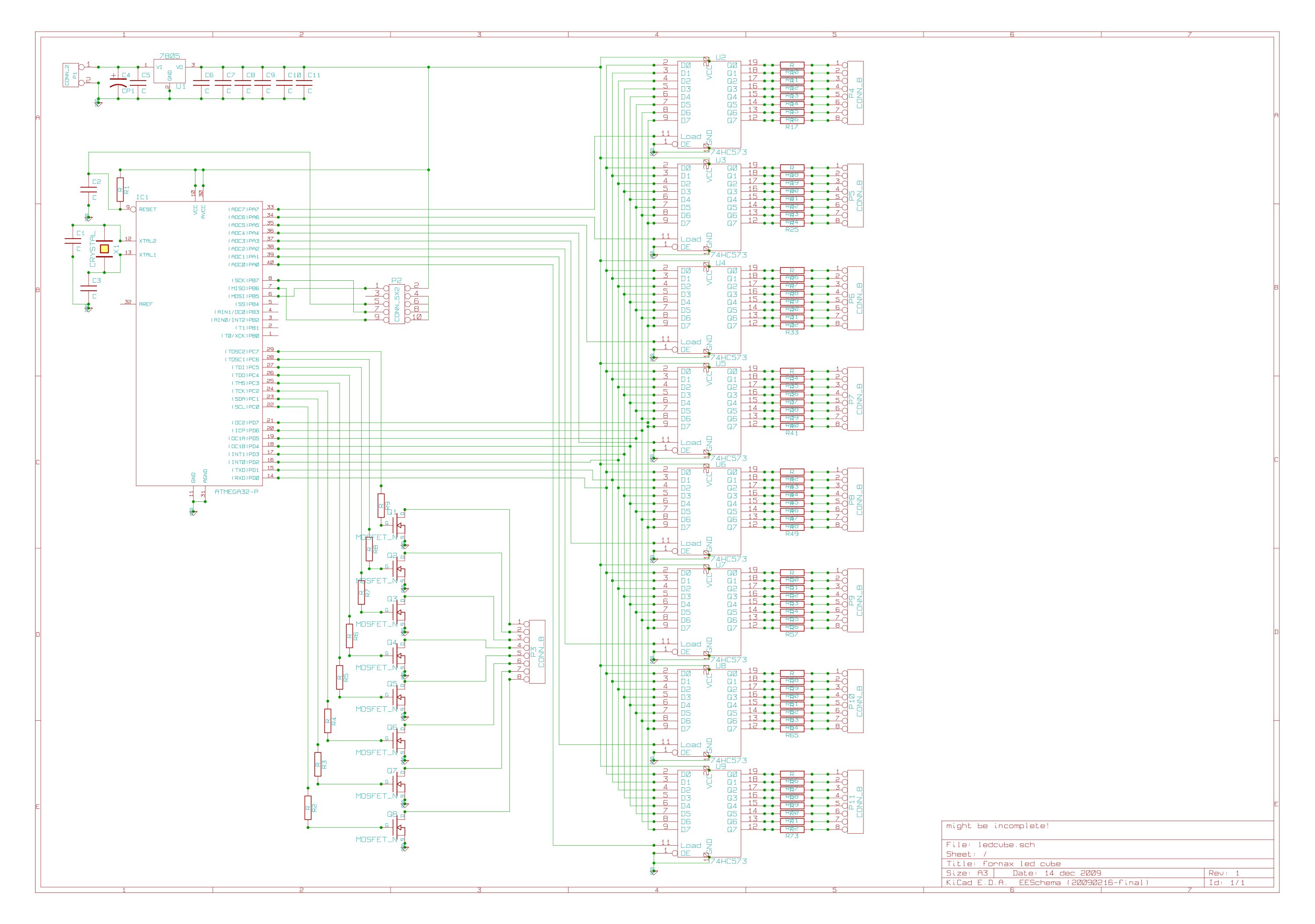
Part list:
C2: 10p
C4: 100u
C5: 0.33u
C6-C11: 100n
P1: 2 pin header (VDC input)
P2: 2x5 pin header (ISP)
P3: 8 pin header (layer ground)
P4-P11: 8 pin header (vertical anode)
Q1-Q8: n-mosfet (at least 0,5A)
R1: 100k
R2-R9: ~1k (depends on used FETs)
R11-73: LED resistors, limit current for each led to 8.75mA (measuring is the easiest way)
U1: 7805
U2-U9: 74HC573
IC1: ATMega32
X1: 16MHz
Since a lot of people asked me about the FETs: I suggest IRLZ34N, IRLU2905 or IRLIZ44N with 1k resistors.
Software
Get the source code!
If you have ideas or annotations regarding the code, just email me (fornax at leyanda.de). The cube is organized in a uint8_t [8][8] array, so one frame takes only 64B. This is useful for calculating transformations, or even simple hardcoded animations stored in the flash. The remaining axis for the 3D-cube are the bits themselves. That means I can send the var directly to the port register (to the 8bit d-latches). It takes no more than 70 asm statements to show one frame. I am using an interrupt based viewing as well as a dedicated loop, depending on the current animation (some functions flicker with ISR).