

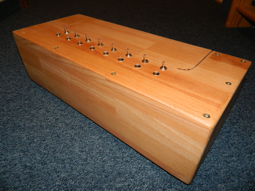
Useless Machine Advanced Edition

Overview
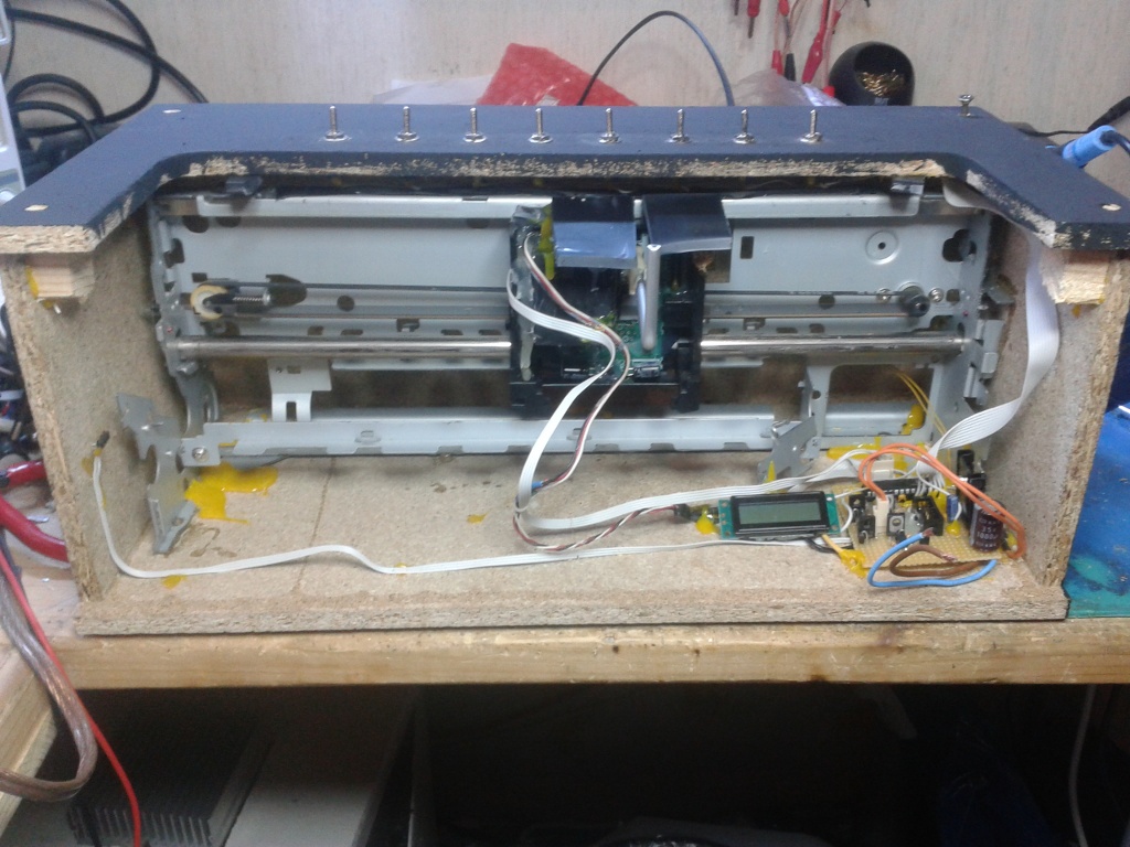
I had the idea for making this machine back in 2011 when my printer (Canon 850i) stopped working because of a broken printhead. The rest worked quite fine, so why throw it away?
This machine recently got a lot more attention than I had expected and several people asked me if I would sell these devices. I am not going to make a business out of it, but if you really want one, you can contact me at fornax (at) leyanda.de. Please keep in mind that it's a highly custom design for each one (takes some time and it's not going to be a mass market price). I can also offer assembled or blank controller units (see below) if you want to try it yourself.
In case you were wondering: I am the original creator of the multi switch advanced version, but not the single switch one which dates back to about 1950. And yes, I am genuinely happy about all clones made by other people (made one? mail me!).
Watch the video on youtube
More Machines


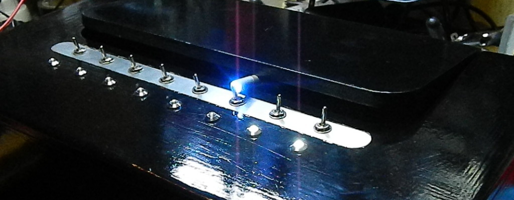
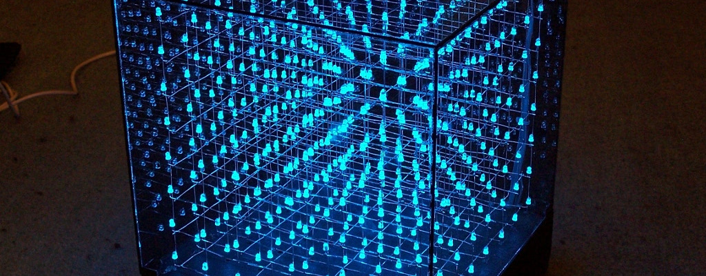
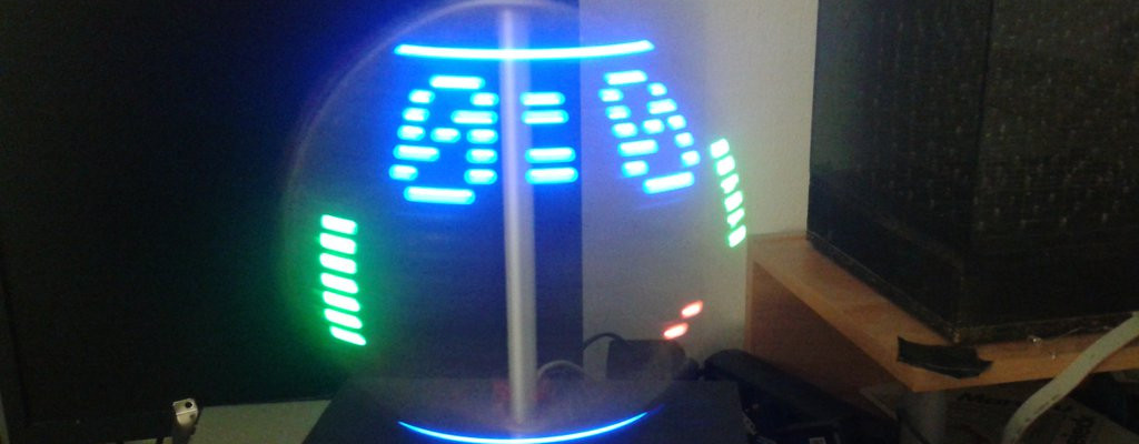
Some pictures of other versions of the machine, including some LED effects and a regular one with a boxing glove.
Controlling the slider
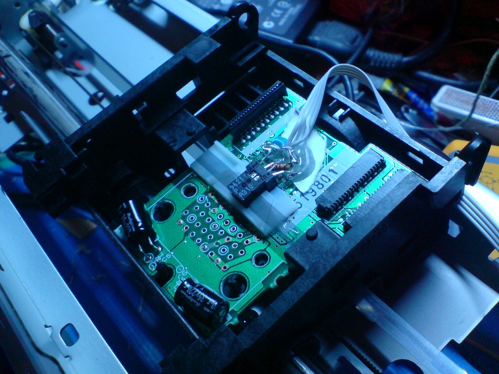
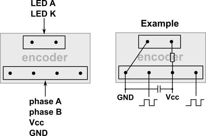
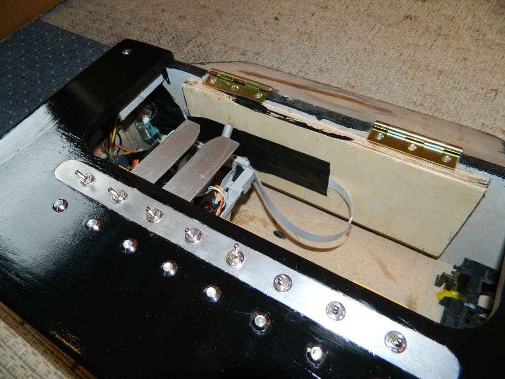
The printer uses a regular DC Motor with belt and an optical incremental encoder to control the slider position. Since the controlling stuff of the printer was completely integrated, I had to build my own one. Fortunately, I could find a datasheet for the encoder (Agilent AEDS 9621P). These detector units are directly TTL compatible, you just need the supply voltage and can read out stable phase signals. The resolution is about 237steps/cm.
After disassembling numerous printers, I can confirm that most oft them look very similar. The encoder usually comes with 6 pins in 2 rows. Some hints:
- in the 4 pin row, look for 2 pins that are connected to a SMD ceramic cap somewhere close. Those are Vcc and GND.
- Often, they are already connected via a resistor somewhere on the pcb to the LED pins (2 pin row).
- If so, try to find out the LED polarity and carefully apply voltage to Vcc and GND. Start with 3.3V and limit to 15mA.
- If not, try to find other hints like electrolytic caps for the polarity and connect the LED via an external resistor
- If the printer is not older than 15 years, it will most likely work with 3.3V. Be careful with 5V.
- Wire everything via the flexprint cables, use multiple parallel wires for the servo power. Use the original connectors (unsolder with a hot air gun if necessary).
- Some printers connect the encoder wires directly to the flexprint cable. Make use of that.
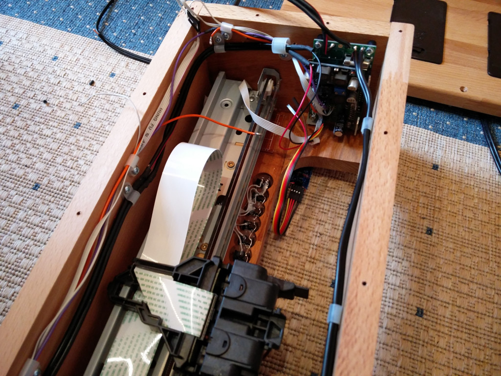
Servo
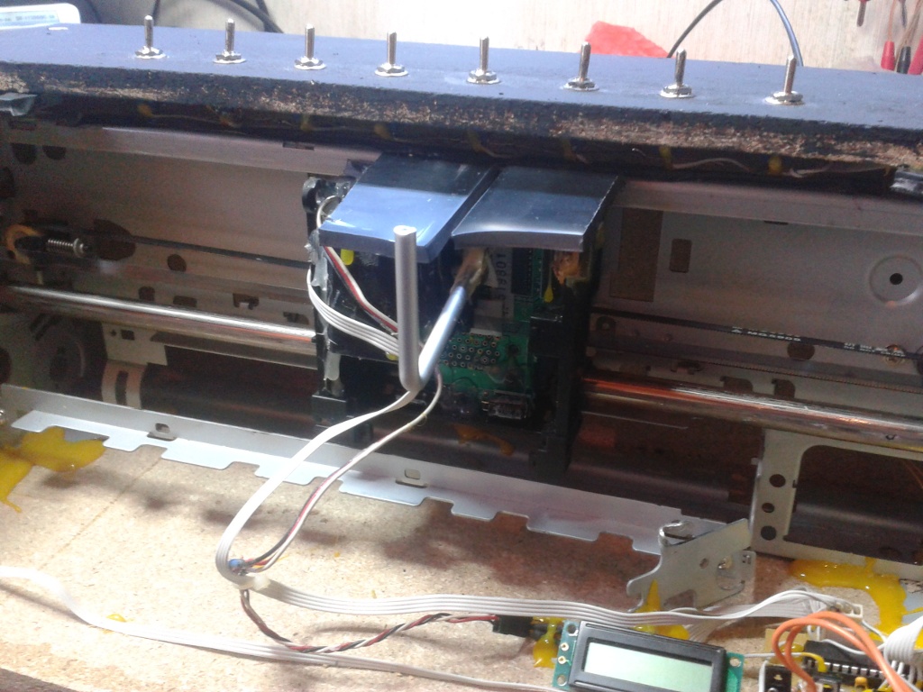
As you might see, I didn't put too much effort into this part, just a short bar glued to a RC servo. The black parts are used to reduce the torque while the slider is moving (with the bar pressed agains the lid). I planned to use another servo for opening the lid, but this was not necessary since the first one is strong enough (plus, one 7805 is not enough for 2 servos). I figured it works quite well when you glue the bar to the servo arm with epoxy adhesive and a few cable ties.
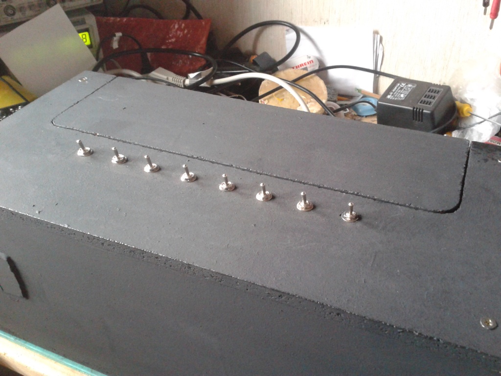
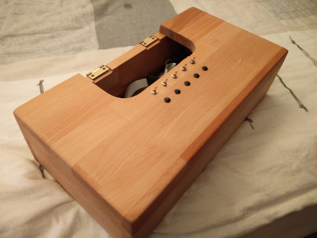
Switches
The switches are standard toggle switches, seperated from GND when active (internal pullup in the ATMega).
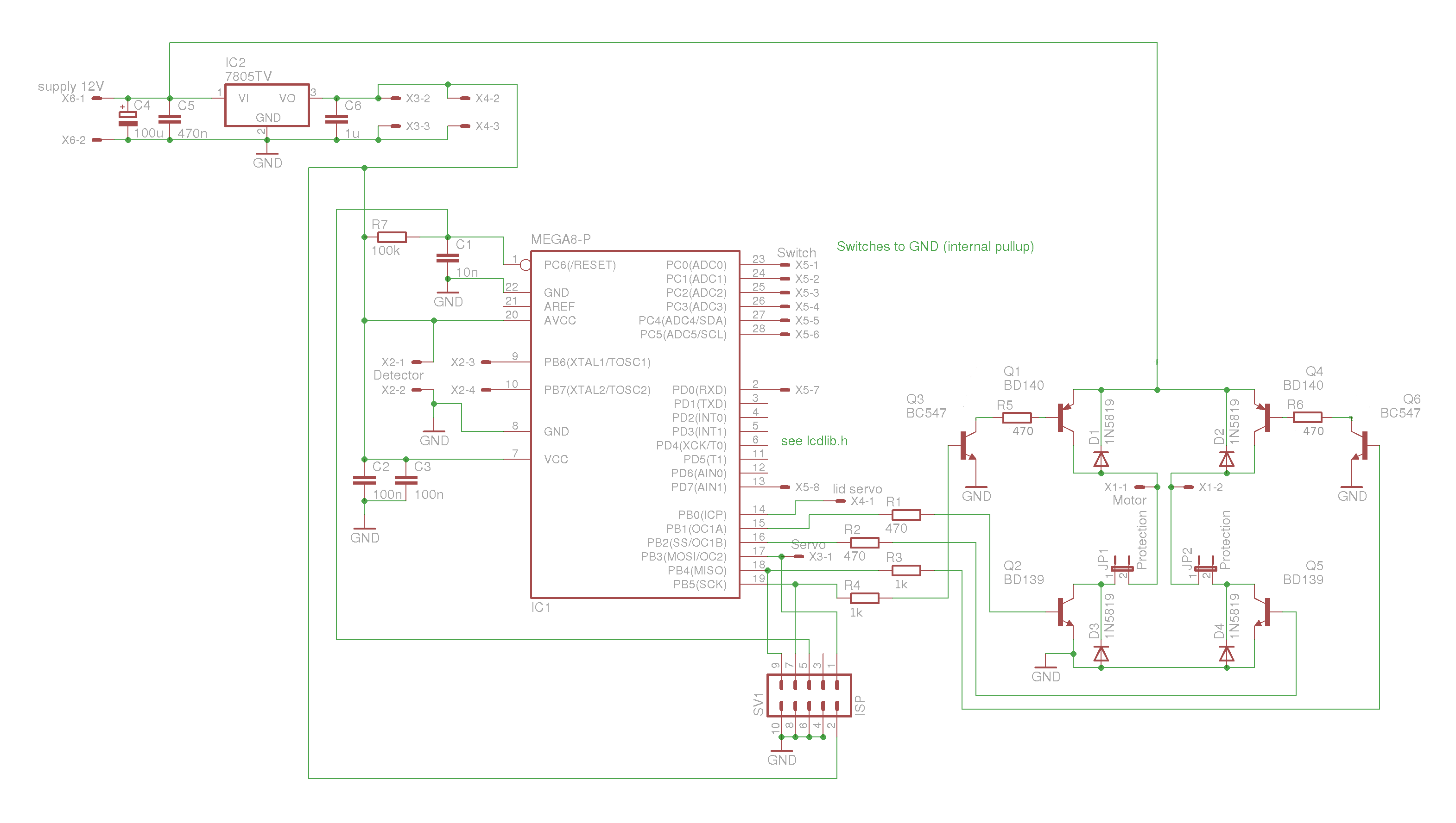
Control Unit


The first version of the control unit used these parts:
- ATMega8
- H-bridge for the motor (I actually used BD137+BD138)
- LCD (to be able to set the switch positions)
- PWM outputs for the servos (the one for the lid is still there)
- inputs for the encoder
- inputs for the switches, internal pullups
- 7805 voltage regulator
Here is the first schematic
There was a small mistake in the connection of the PNP base resistors, which is fixed now (6.12.2011).
I included 2 jumpers to avoid short circuits in the H-bridge while flashing.
In the meantime I designed a newer one on a single and one on a dual layer pcb. Here are the features:
- 5V-7V power supply for the Servo
- Selectable 3.3V and 5V power supply for different printers
- Automatic toggle between battery supply and external power
- Buckboost driver to get constant voltage even with batteries
- L298 as H-bridge
- Shift register for 8 LEDs
- UART position output
New schematic.
It can easily be stripped down to the parts you need. What might get changed in a later revision are the connections on SW0/1 (both need to be activated for flashing, which is annoying) and a voltage monitoring, because the voltage converters are not fail safe.
Software
When powered on, the controller moves the slider to the left to set zero position. The positioning itself is done by a software PD controller, which is able to set the slider in less than 1sec with an accuracy of about 0.1-0.2mm. I could reach even better precision, but for this task it's more than enough. In the original version, the highest priority was on the left side, I adapted this to follow the order the switches have been activated.
The code should not be too hard to understand anyway, Note that the pin declarations of this version do not match the new schematic yet.