
Light
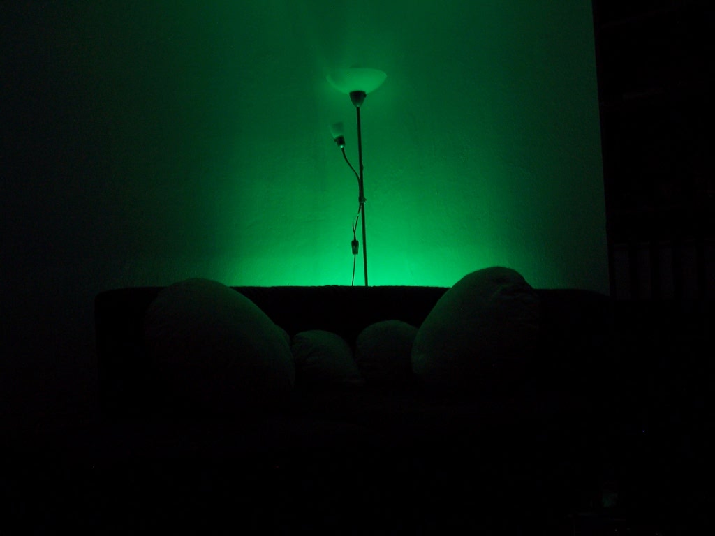
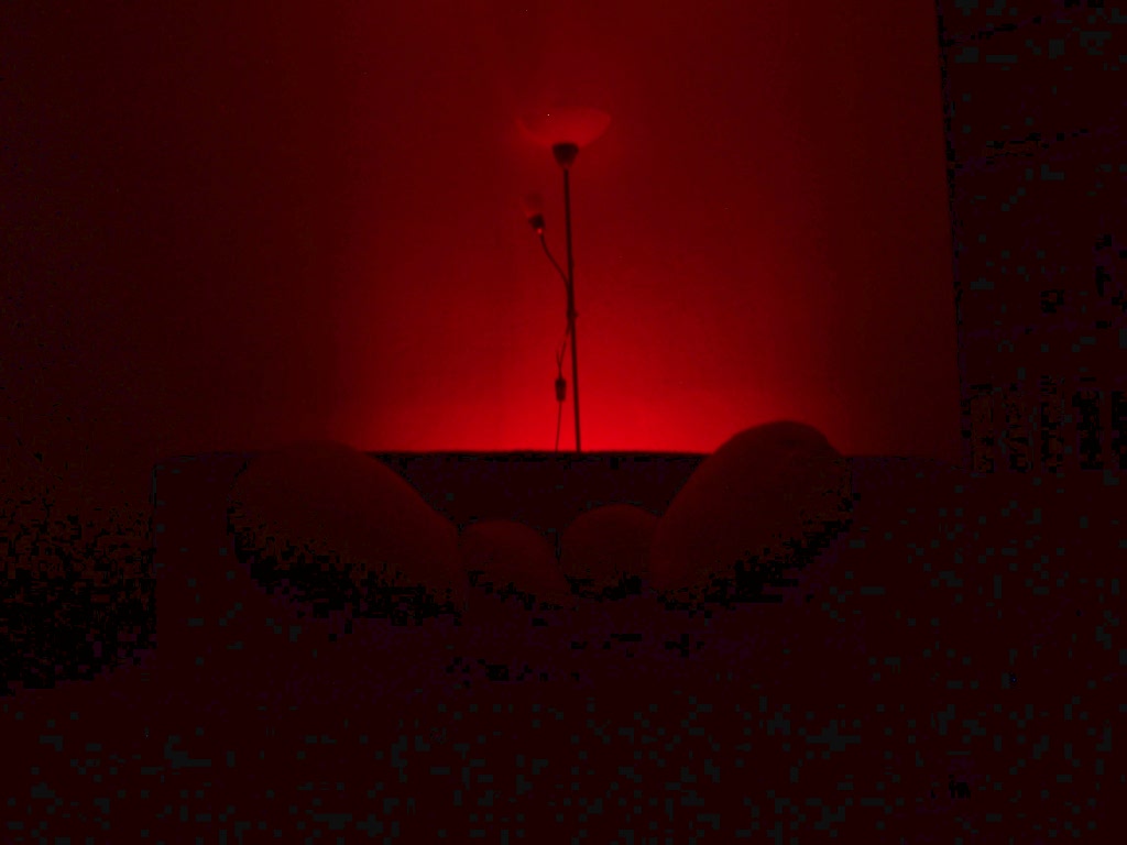
RGB mood light

Overview
I've created a lot of simple RGB controllers before there were satisfying, commercial solutions available.
This one was my last attempt from 2007 to make a universal, simple controller without unnecessary features.
The device is somehow obsolete now since I switched to the milight system.
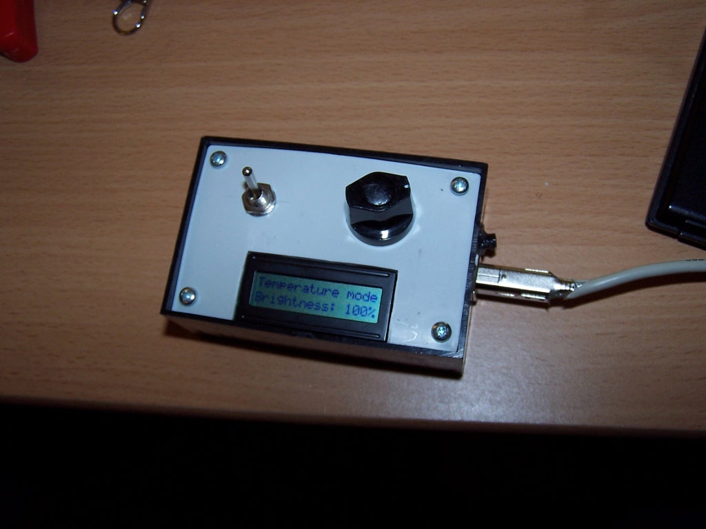
Features
- a set of predefined colours
- LCD
- rotary encoder
- seperated control unit/driver
- remote control
- smooth fading (0.5s) between manual color select, non-blocking
- autofader (~5s), using predefined colors
- temperature control
- manual RGB level mode
- random colors
- logarithmical brightness control for each mode/color
- NO annoying flash/strobe effects
Example Setup


More Details
- predefined colors
- seperated control unit/driver
- fading
- temperature control
- logarithmical brightness control for each mode/color
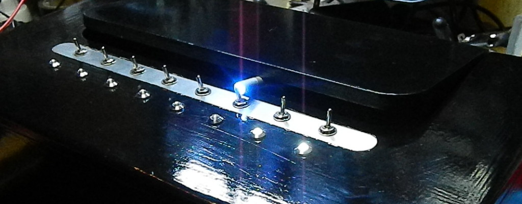
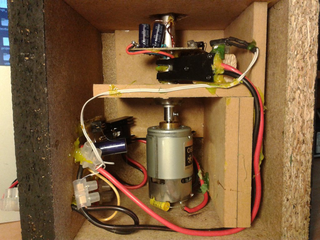
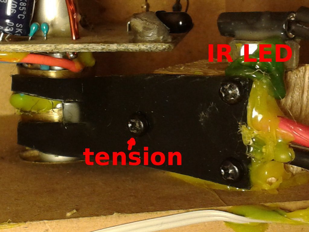
Control Unit
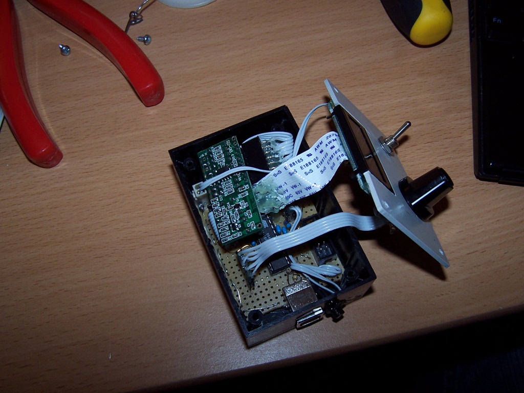
Schematics still need to be drawn :)
source code
Note: this is an old beta with linear scale, the most recent version will follow soon.
The lcd lib works for hd44780 lcds.
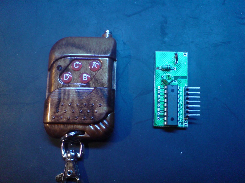
Remote Control
Temperature Sensor
The sensor is a KTY81-120, wired this way:+5V--R10k--ADCin--KTY--GND
Of course, not very accurate, but enough for this purpose.
Driver
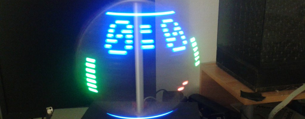
POV Globe
Overview
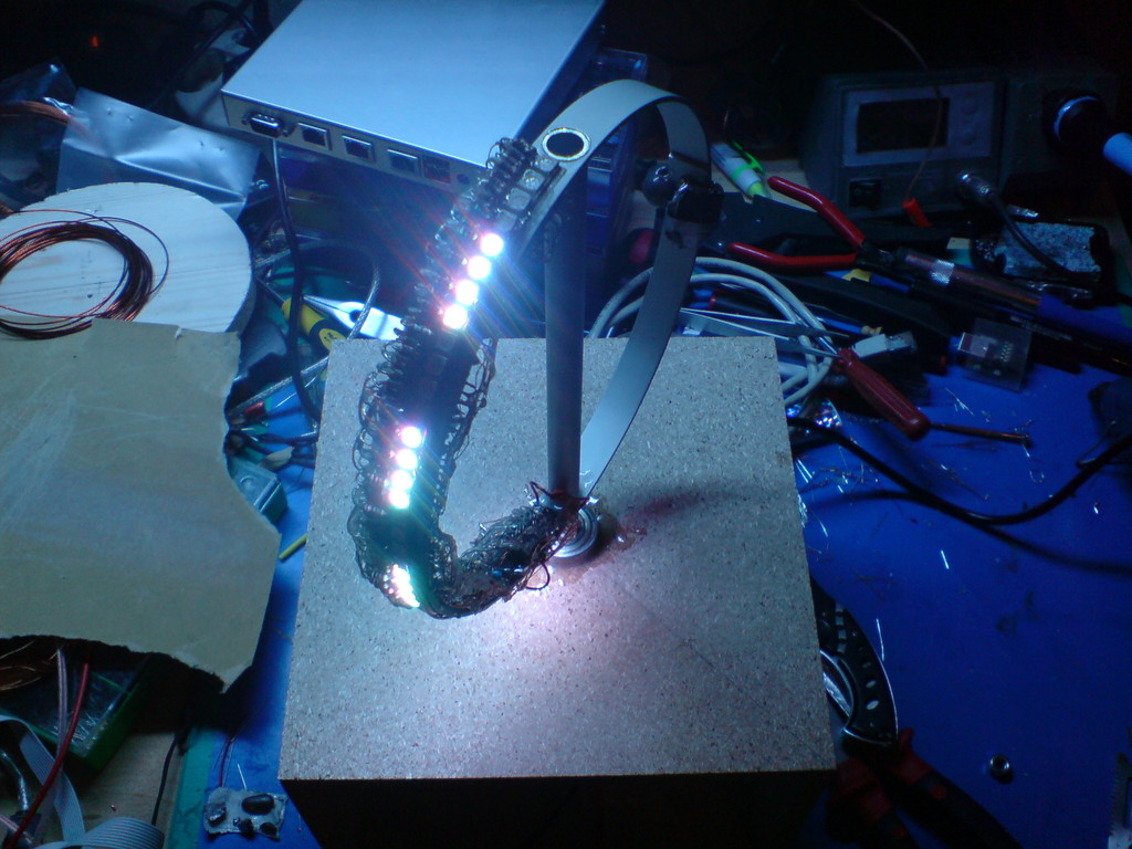
A POV globe display with 40 RGB LEDs.
On this page I will try to show you the features and how I built it. Please note that this page should not be considered as a step by step tutorial.
Deutsche Beschreibung: auf mikrocontroller.net


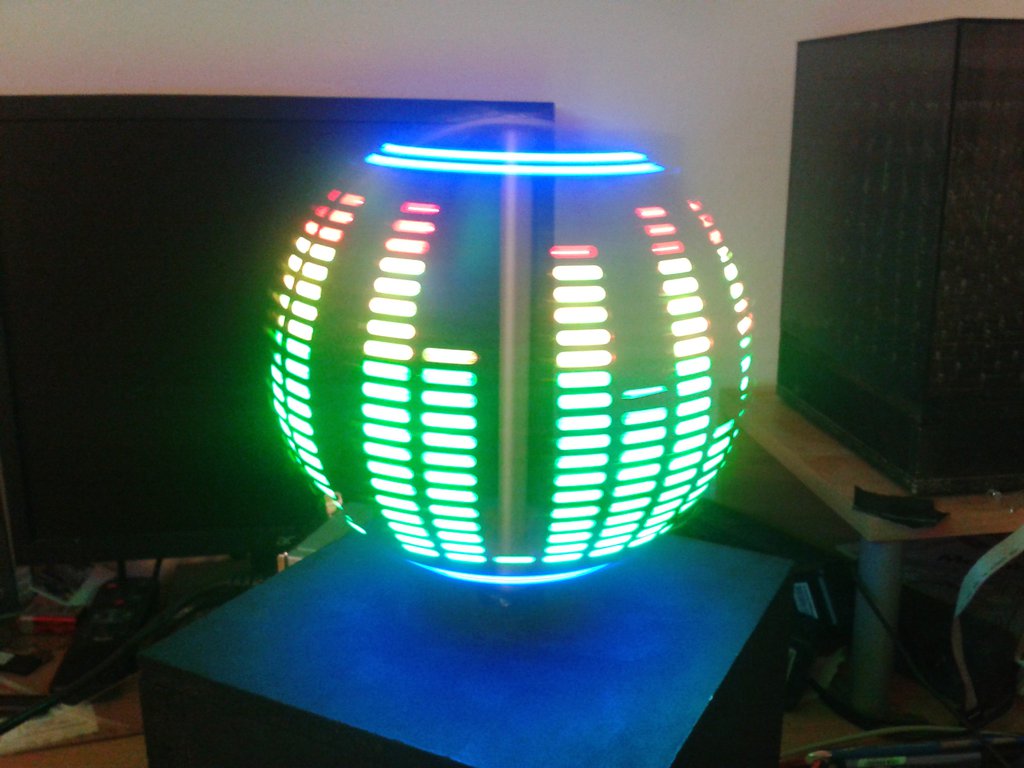
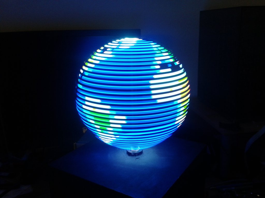
Animations/Effects
Here are just some of the effects I wrote for the globe. Youtube link
- animated text: there are several text animations with different colors, rotation speed etc.
- earth map: of course, a globe should feature an earth map. I wrote an image converter for this
- Pong: a simple version of Pong with 2 AI players
- Pacman: a Pacman eating dots around the globe
Construction
Rotor
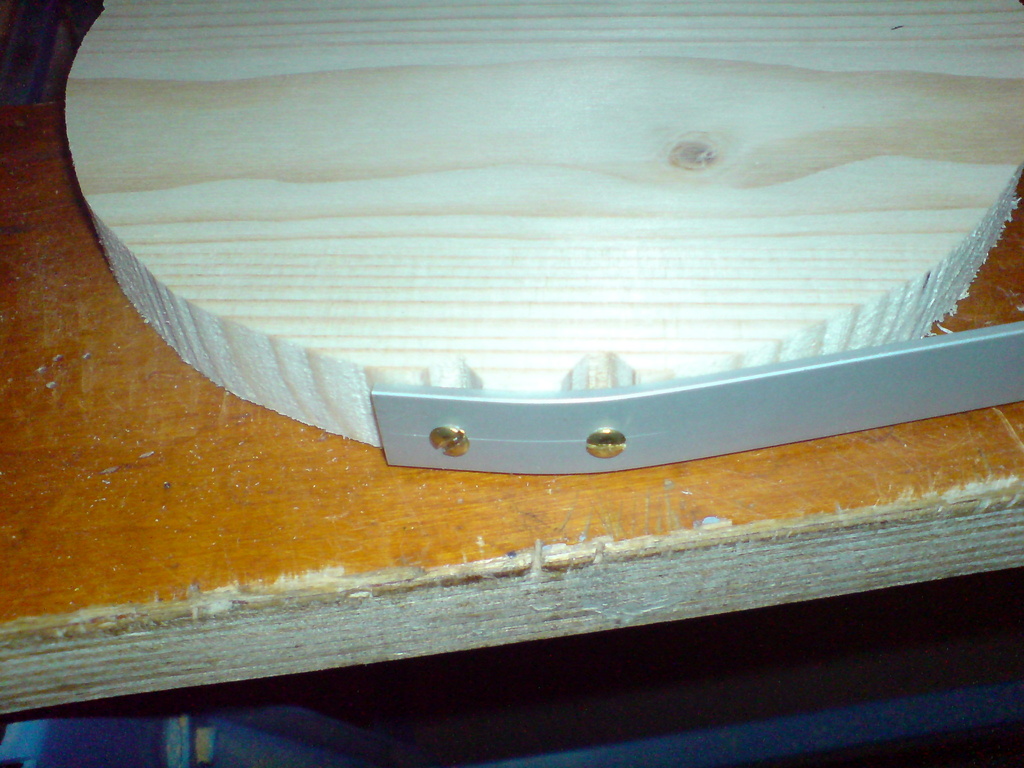
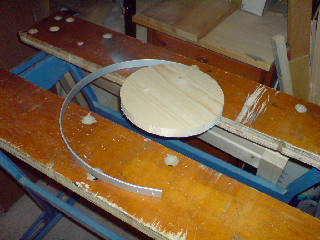
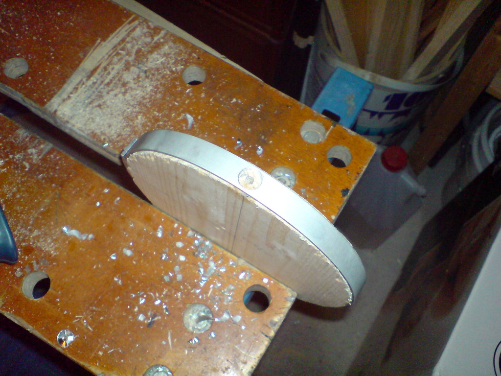
Let's start with the rotor. It is made of a 15mm aluminium bar and a 12mm aluminum tube.
The diameter of the rotor is about 200mm, so I cut a fitting slice of wood. The ends should overlap some cm so they can screwed together. I also cut some smaller slices for bending, until the diameter of the rotor after bending was ok and without tension (important because of the 2 holes).
After that, I fit the ring onto the 200mm wood slice and drilled the 12mm holes for the tube. The tube is about 300mm long, just long enough for mounting 2 ball bearings, the controller pcb and the sliding contact.
Both parts were glued together with epoxy.

LEDs and shift registers
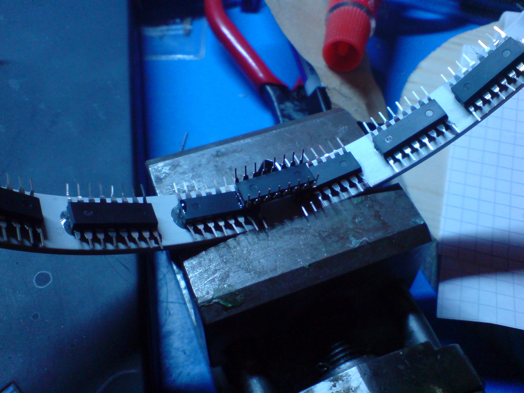
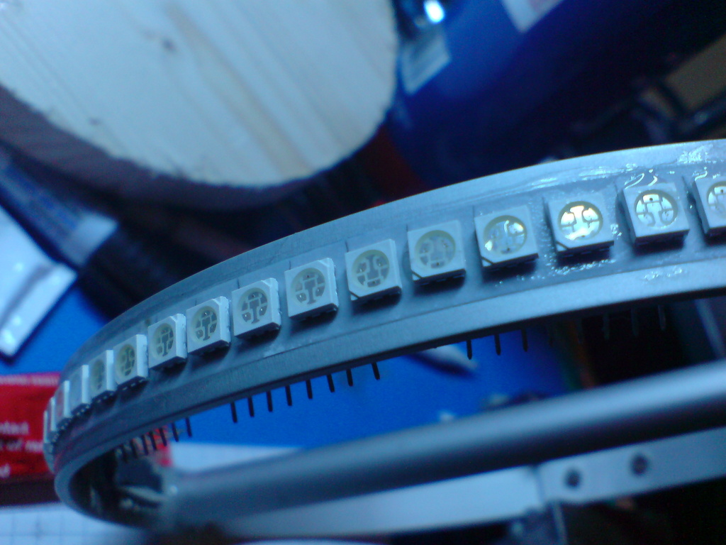
The LEDs are SMD RGB LEDs (5050,PLCC6), these LEDs are bright and have 3 seperated anodes and cathodes. I used 15 74HC595 shift registers, 5 in series for each color. Each register can take up to 70mA on the Vcc and GND pins, so if I want to drive the LEDs with nearly 20mA I have to connect 4 LEDs common anode and 4 common cathode to each register.
This leads to 2 things: since I reversed the pins this by rotating the LEDs by 180deg, the green and blue pins are flipped. Second, 4 LEDs are active high, 4 are active low. You have to take care of this in the software.
See the rotor schematic (in the .tgz) for the wiring of 8 LEDs, the whole unit is used 5 times and the registers are connected in series (for each color).
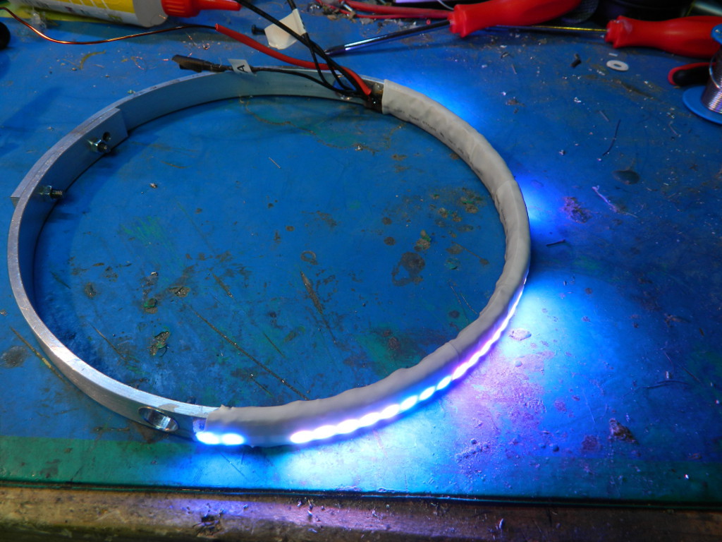
The supply and bus lines can be passed through 2 holes inside the tube. After mounting, connecting and testing everything I used a large amount of epoxy to cast everything and make it rugged. Note: SMD resistors would be a better choice.

Motor
The motor needs active cooling.
Power Supply
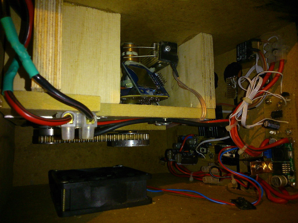
Controller Board
The controller board is very simple. The ATMega644, some capaciators to stabilize the power supply (sliding contact!), and a dual opamp to amplify a photodiode. This diode is used to detect the zero position and also control the refresh rate.Schematics and pcb layout are included in the .tgz. Please note that the component placement is seen from the copper side, I only mirrored the parts where it matters.
The labels in the rotor schematic show the name of the right controller pin, too.
Software
The Software is written for avr-gcc with avrlibc and make.I use an array: uint8_t globe[80][5][3] as the display buffer. The first value is the x/longitude position, the second one the vertical line (like a graphic LCD), the third one is the RGB color index. Each byte in this array are the vertical pixels on this position (again like a graphic LCD).
The actual image generation is done by two ISRs. One timer ISR with variable cycle duration, it contains a counter which counts 4 times faster than the output function is called. Another (external) ISR is triggered when the rotor reaches zero position. This routine resets the counter and also sets the refresh rate by checking the value in the counter.
The output function just pushes the current logitude into the shift registers.
Image Converter
I wrote an image converter for perl and imagemagick which converts a 80x40 bitmap to a header file which will store it in the flash. One image will need a little more than 1.2k of flash.Please note that this script is a quick and dirty hack, don't expect any error checking.
You can set the threshold values for each color in the script, this is important since the globe supports binary color values only.
The converter will also generate an image that allows you to check the thresholds without uploading the file.
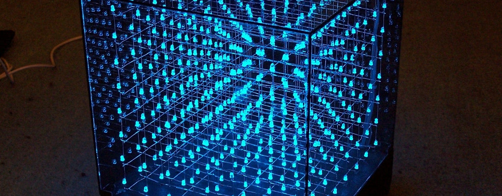
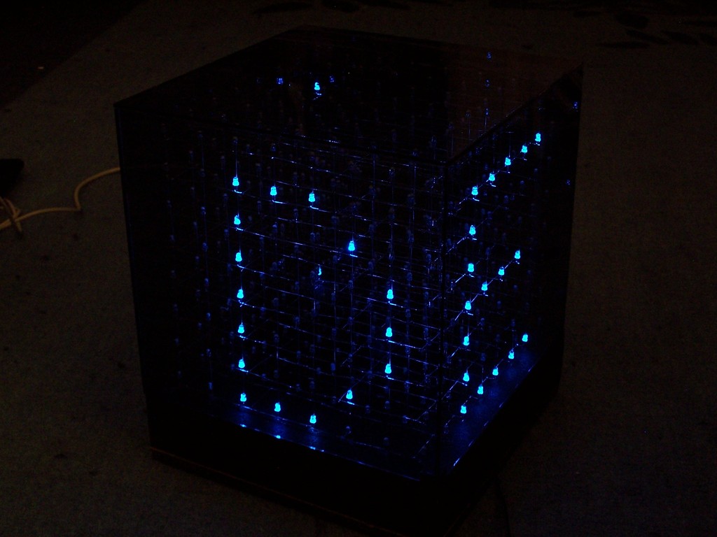
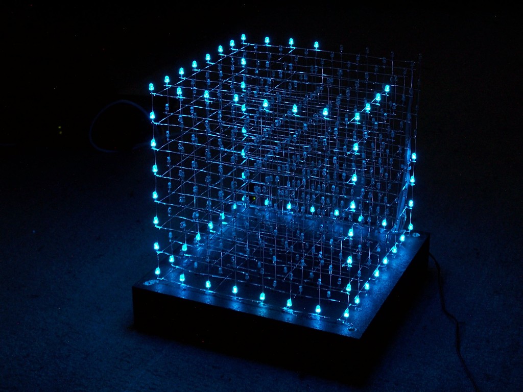
8x8x8 LED Cube
Overview
Another LED cube project, based on an ATMega32 controlling 512 blue 3mm LEDs
I've put a lot of time and work in the animations, but I think it was worth it.
Deutsche Projektbeschreibung auf mikrocontroller.net
Animations/Effects
The software supports a large set of different animations, here are some of them.
Better watch the video...
- animated text:
All text functions support [A-Z][0-9][?.:!]
In this case each char comes in from the left side, rotates by 90 deg and is then moved to the front with some flash effects.
- text back to front:
Each char starts at the backside and moves quickly to the front.
- text belt:
Actually this is a 25x8 pixel layer which is mapped around the left/front/right of the cube. The string moves from the right to the left.
- 2 chars rotating:
2 fixed chars rotate around the center.

- walking man:
This is a really cool animation. At first, a door opens and a guy walks in. When he reaches the center, the environment starts moving while he walks, after some time it stops and the guy walks out of the cube.
- 2x2x2 cubes:
24 2^3 cubes moving around, fully automatic. For this effect an extra cube of [4][4] is created where the elements represent 2^3 cubes. This is later mapped to the large cube. Now one element and a direction is chosen by rand(). The cubes are moved until they hit the "wall" or another cube.
Watch the video on youtube
Construction

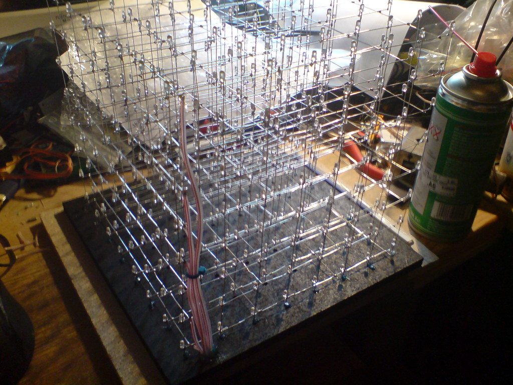
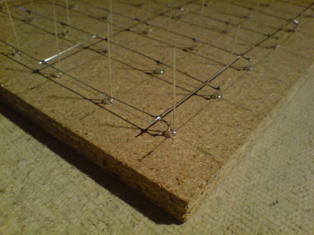
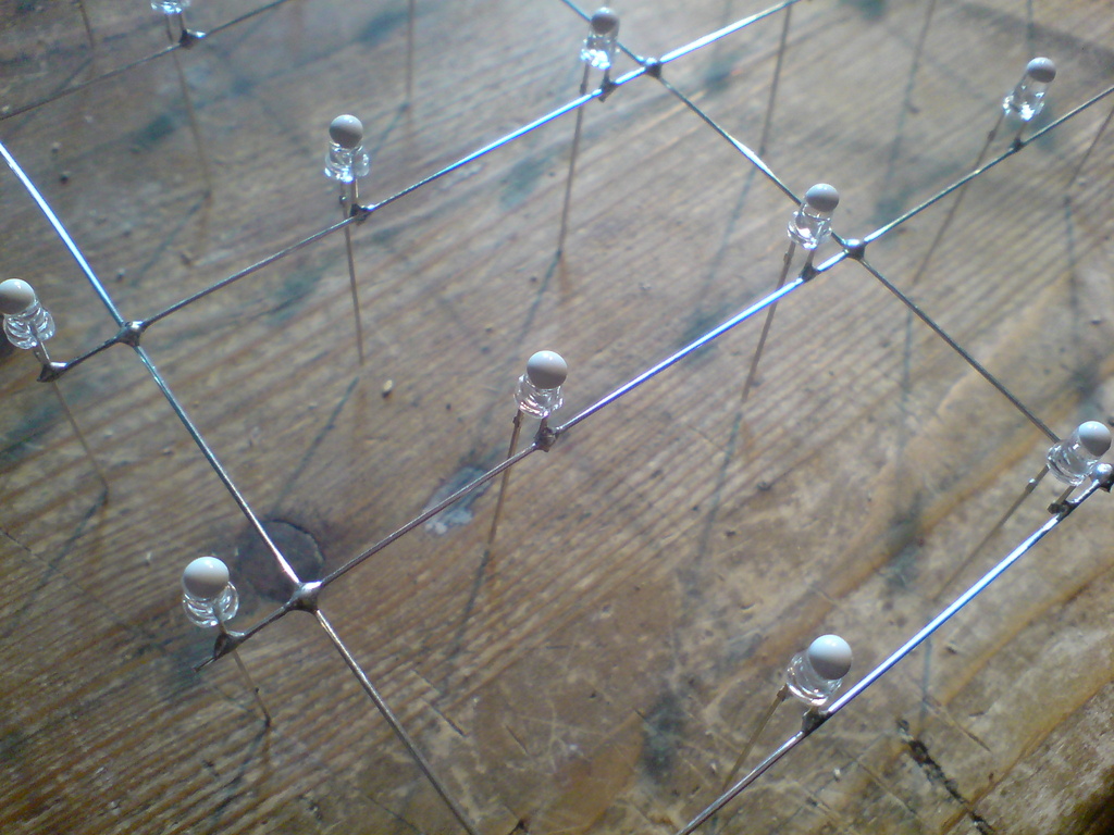
I started with drilling 64 3mm holes (distance between the holes is 30mm) in the ground plane, which is very helpfull for soldering the layers.
The cathode pins were cut and soldered together with 0,6mm silver wire.
I ordered 600 LEDs, that came in handy since some LEDs were broken and some were killed with the soldering iron (I soldered very close to the housing). This way I got exactly the same wavelength and brightness for those LEDs. And by the way, replacing a LED inside the cube is no fun, although its possible with a steady hand, a long soldering iron and tweezerz :)
Each layer was tested and finaly all layers soldered together.
I painted the ground plane black and glued the cube in it. Grey tinted glass is used for the cover.
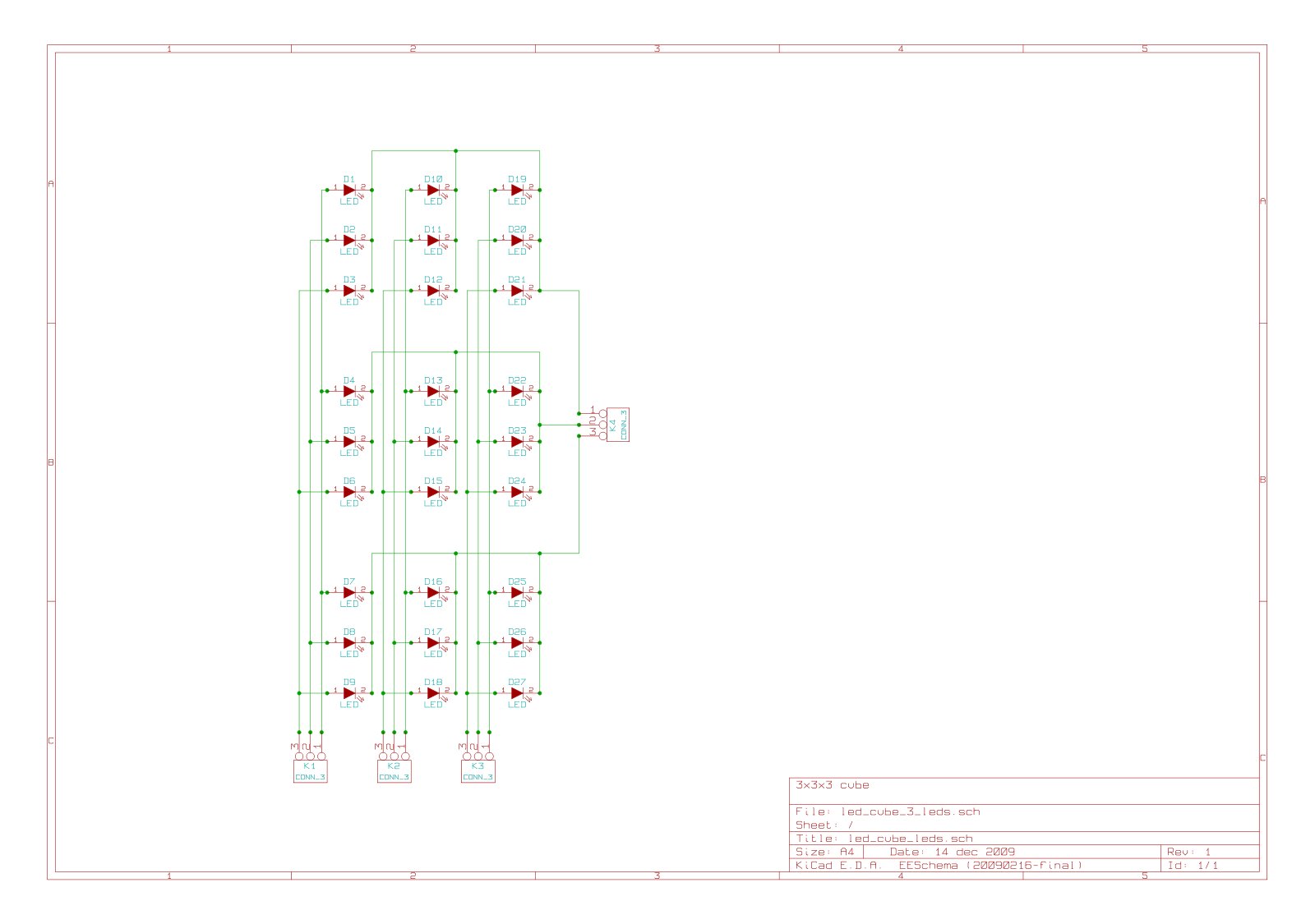
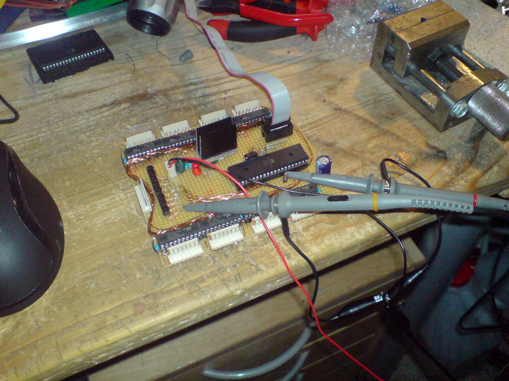
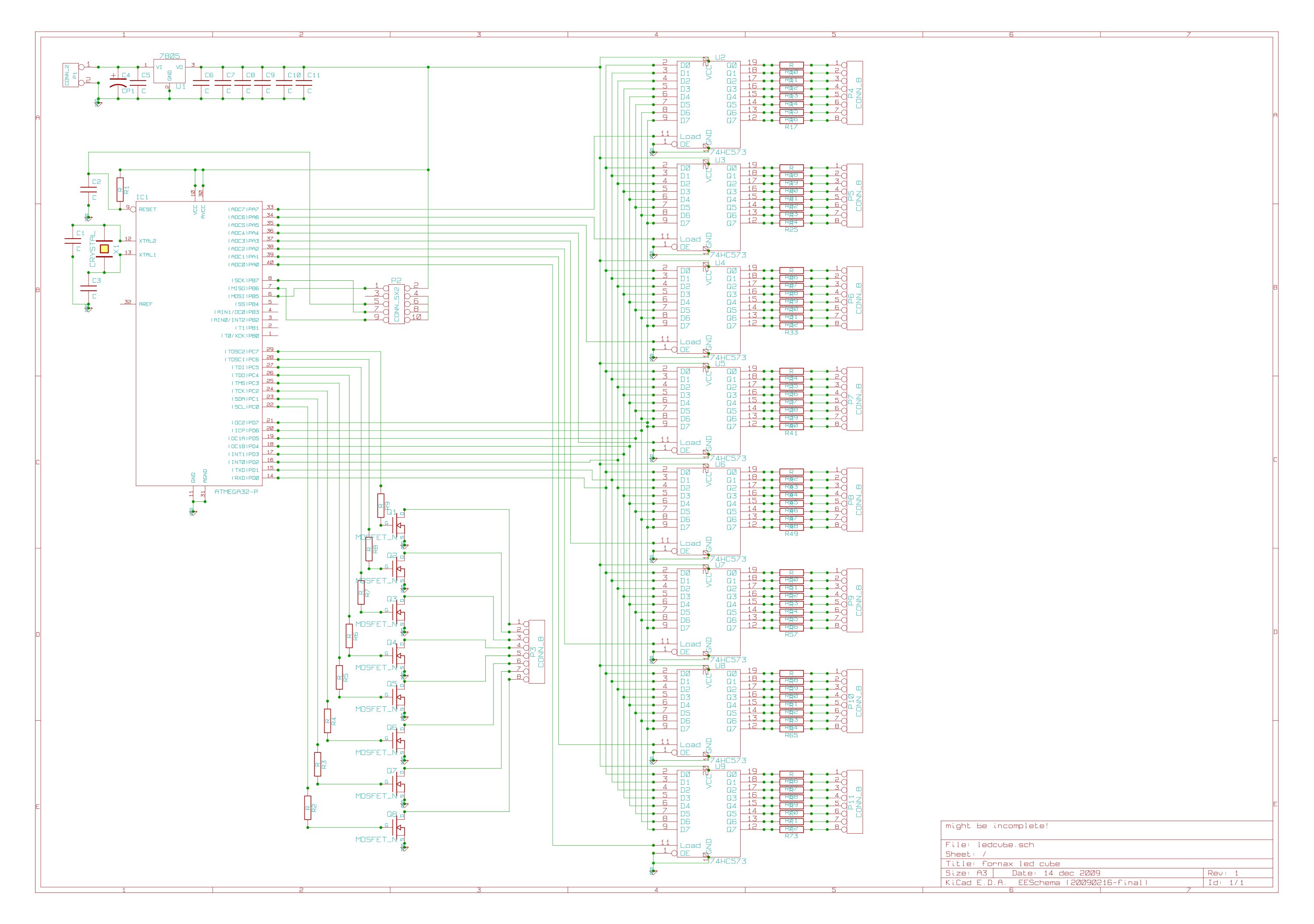
Control Unit
The control unit is quite simple, 3 ports of the Mega32 were used:
- one port controls 8 FETs for sinking the 8 ground layers
- one port is wired to all 8 8bit d-latch inputs
- the last port is used to enable the d-latch inputs
Since the d-latches are only able to sink or source 70mA on all 8 latches, I had to limit the diode current to ~9mA, which is fairly enough for this type of LED.
Here is the schematic for the controller board: scheme.
For my source code, the wiring should be like this: PC0 is the bottom layer, PC7 the top layer.
PD0 (Q0) sets the front bits, PD7 (Q7) the rear side. PA0 (U9) is the left side, PA7 the right side.
Part list:
C2: 10p
C4: 100u
C5: 0.33u
C6-C11: 100n
P1: 2 pin header (VDC input)
P2: 2x5 pin header (ISP)
P3: 8 pin header (layer ground)
P4-P11: 8 pin header (vertical anode)
Q1-Q8: n-mosfet (at least 0,5A)
R1: 100k
R2-R9: ~1k (depends on used FETs)
R11-73: LED resistors, limit current for each led to 8.75mA (measuring is the easiest way)
U1: 7805
U2-U9: 74HC573
IC1: ATMega32
X1: 16MHz
Since a lot of people asked me about the FETs: I suggest IRLZ34N, IRLU2905 or IRLIZ44N with 1k resistors.
Software
Get the source code!
If you have ideas or annotations regarding the code, just email me (fornax at leyanda.de). The cube is organized in a uint8_t [8][8] array, so one frame takes only 64B. This is useful for calculating transformations, or even simple hardcoded animations stored in the flash. The remaining axis for the 3D-cube are the bits themselves. That means I can send the var directly to the port register (to the 8bit d-latches). It takes no more than 70 asm statements to show one frame. I am using an interrupt based viewing as well as a dedicated loop, depending on the current animation (some functions flicker with ISR).
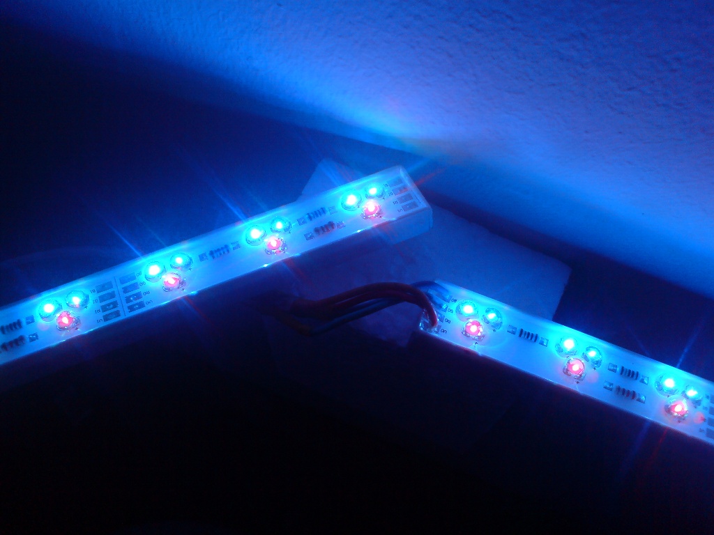
LED Bar
Overview
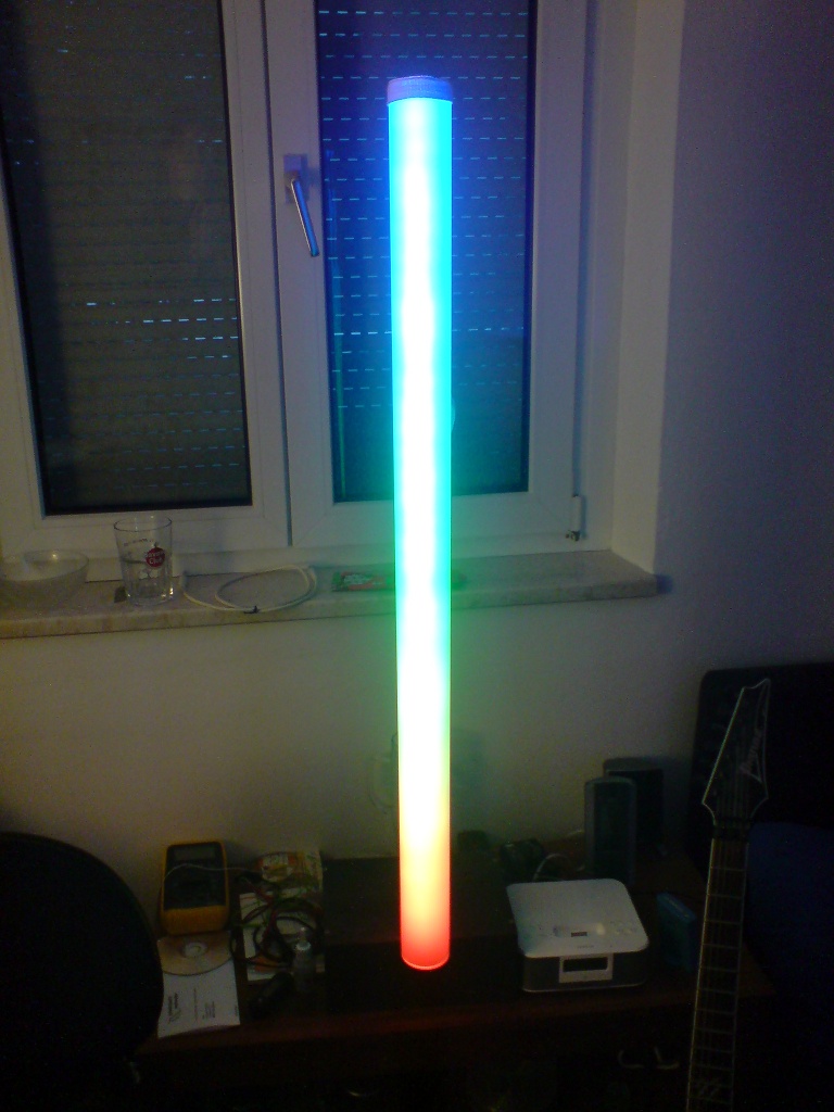
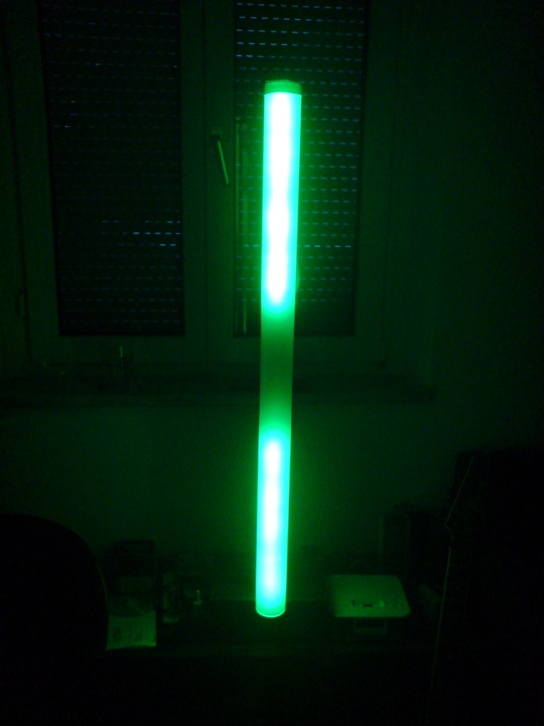
Features:
- 40 RGB LEDs
- 64000 colours per LED
- full brightness on each LED/colour possible
This project was inspired by some larger light effects I've seen on buildings. I decided to try aranging 40 RGB LEDs to a 1m bar and see how it looks.
Please note: I still get questions about the schematics. This was one of my earlier microcontroller based projects and is a rather questionable approach (i.e. WAY too much work). Things evolved a lot since then, so if you plan to build something similar, just use a strip of WS2812B LEDs.
Construction
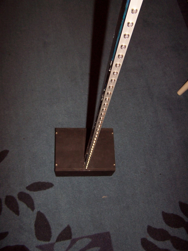
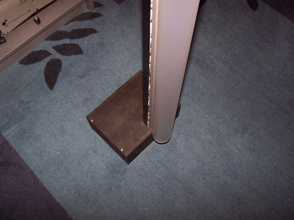
The LEDs are mounted to a 1m aluminium profile (u-shaped). It was some work to solder the 120 wires...
This version did not look bad, but multi chip LEDs do not mix the colors properly, so I bought a 1m frosted acryl glass pipe. Again, not bad, but I figured out it looks best if you mount the whole pipe in front of the LEDs.
Control Unit
I used a ATMega16 for this one, controlling 15 74HC573. In order to get full brightness, I used 18 ULN2003 to sink each chip with full 20mA.
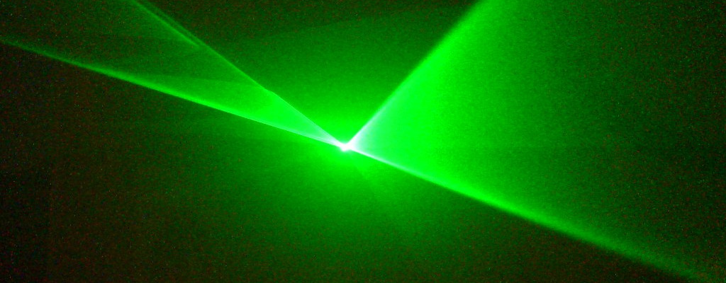
Lissajous Scanner
Overview
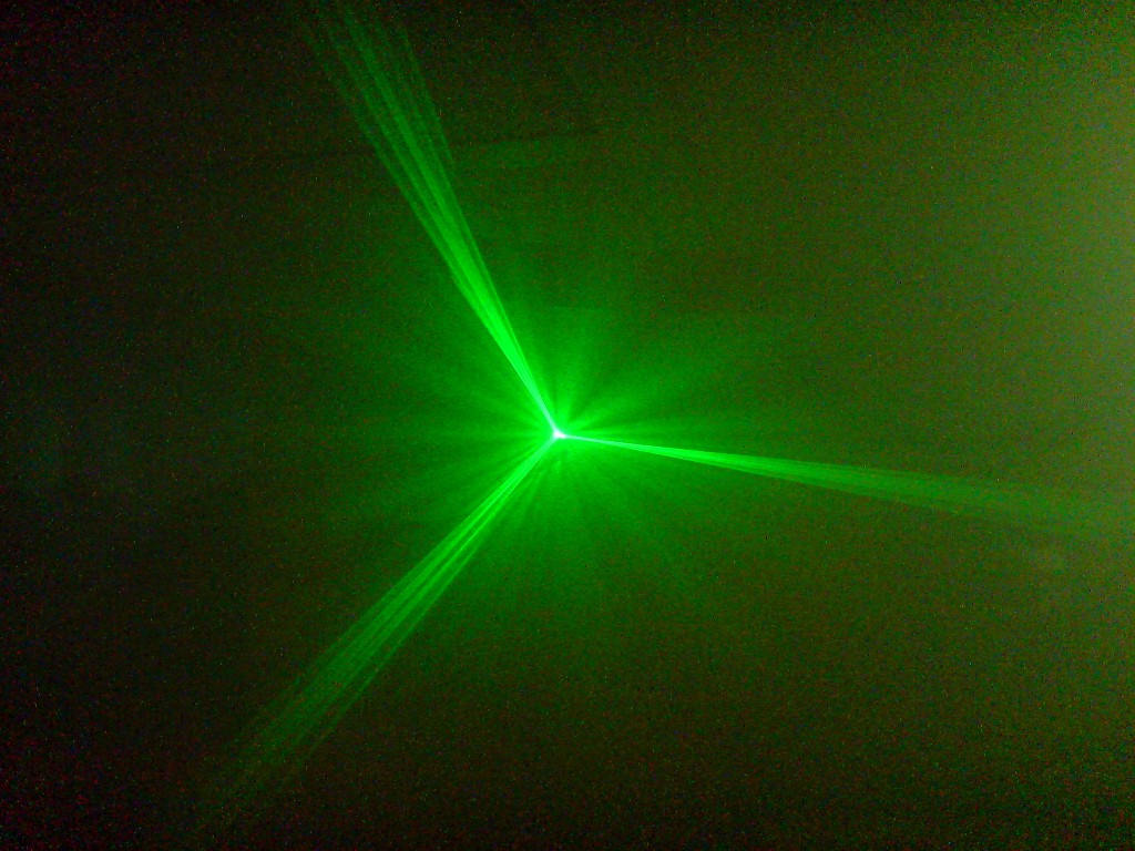

This one started when I found one of those simple lissajous kits I bought years ago. It has 2 DC motors with mirrors on them, you can control their speed and direction with 2 potentiometers. This is unusable if you really want to put the laser as a light effect somewhere, so I build a small controller unit for the motors and the laser. I also replaced the red laser with a green one since they got quite cheap now, are brighter (for the human eye) and the ray is visible even with just 1mW due to the greater rayleigh scattering.
Controller

The controller is based on a ATTiny26. Two PWM channels are used to set the motor speed. The direction of one motor can be reversed, this is done through a dual relais (I lacked enough PNPs to build a h-bridge). The laser is a green laser pointer, a LM317 is used for the 3.1V power supply, as well as a small FET to switch it on and off.
Sound control
Nothing spectacular, I just use a dual opamp to amplify a microphone with variable sensitivity. The output goes through a simple (3dB 150Hz) low pass to the ATTiny26 ADC input, where a free running ADC sets the speed of one motor, while the other motor runs at a fixed speed.